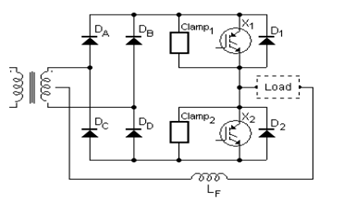
Simplified Half-Bridge Output Inverter Circuit Diagram
submited by
Style Pass
The circuit diagram is called to be Full-Bridge simplification since the number of equivalent Insulated-Gate Bipolar Transistor (IGBTs) is now a half even the number of diodes in the output rectifier is doubled.
When one of IGBTs is in ON, the other is OFF. During the positive half wave, X1 is ON and X2 is OFF so that DA and DB work as output rectifier while DC & DD are OFF and vice versa.
Read more unboxing.eu....


