What’s The Deal With Square Traces On PCBs
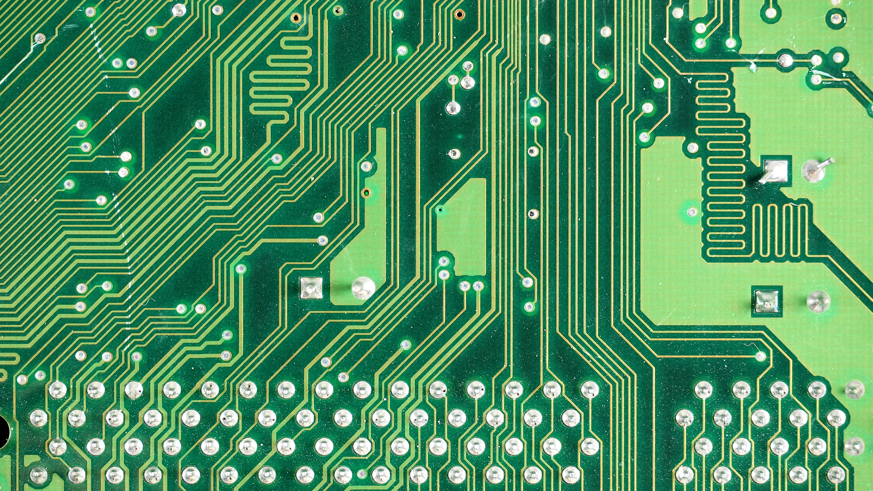
When designing a printed circuit board, there are certain rules. You should place decoupling capacitors near the power pins to each chip. Your ground planes should be one gigantic fill of copper; two ground planes connected by a single trace is better known as an antenna. Analog sections should be kept separate from digital sections, and if you’re dealing with high voltage, that section needs to be isolated.
One that I hear a lot is that you must never put a 90-degree angle on a trace. Some fear the mere sight of a 90-degree angle on a PCB tells everyone you don’t know what you’re doing. But is there is really no greater sin than a 90-degree trace on a circuit board?
This conventional wisdom of eschewing 90-degree traces is baked into everything we know about circuit board design. It is the first thing you’re taught, and it’s the first thing you’ll criticize when you find a board with 90-degree traces. Do square traces actually matter? The short answer is no, but there’s still a reason we don’t do it.
The most-cited reason as to why you shouldn’t use square corners on traces is that electrons bunch up on the corners. This is impossible with our current understanding of physics and would break the universe. Fortunately for everyone, you can just rent test equipment that will test a circuit at 20 Gigahertz. If you’re really good, you can find that test equipment in the trash. Earlier this year, [Bil Herd] put square corners to the test by measuring the impedance of a trace that looked like a square wave. At 20 Gigahertz, the effect of square corners was minimal. At lower frequencies, the effect would be less. Don’t worry about square corners on your traces.
